We use cookies to make your experience better. To helps us analyze data about web page traffic and improve our website, we need to ask for your consent to set the cookies.

FREE Delivery on US Orders Over $25
FREE Engineering Services
FREE Graphic Design Assistance
Buy Direct Today

- Home
- Engineering Information
Engineering Information

The IP Standard
International Standard IEC 60529 outlines an international classification system that describes the sealing characteristics of electrical equipment.
The classification system defines the level of protection provided by enclosures to prevent the ingress of foreign objects and moisture into the electrical equipment. The classification system uses the "IP" code, or "Ingress Protection" code, to define the level of seal. The IP code uses a system of two numerical digits to define the level of both foreign object and moisture protection.
Although the IP classification is primarily used for establishing the level of seal in electrical equipment, it is adapted herein for determining the level of seal in passive electrical components.
1st Digit, Foreign Bodies - Degrees of Protection
The first digit of the IP code indicates the degree of protection against solid foreign objects from entering the electrical device. The table below outlines the level of protection against foreign objects for each level.
| 0 | Not protected |
| 1 | Protected against solid foreign objects of 50mm diameter and greater |
| 2 | Protected against solid foreign objects of 12.5mm diameter and greater |
| 3 | Protected against solid foreign objects of 2.5mm diameter and greater |
| 4 | Protected against solid foreign objects of 1.0mm diameter and greater |
| 5 | Protected from the amount of dust that would interfere with normal operation |
| 6 | Dust tight |
2nd Digit, Moisture - Degrees of Protection
The second digit of the IP code indicates the degree of protection against the ingress of various forms of moisture (e.g. drip, spray, submersion, etc.) into the component. Tests to determine the level of protection are carried out with fresh water and do not take into account the use of solvents.
| 0 | Not protected |
| 1 | Protected against vertically falling water drops |
| 2 | Protected against vertically falling water drops when enclosure is tilted up to 15° |
| 3 | Protected against water sprayed at an angle up to 60° on either side of the vertical |
| 4 | Protected against water splashed against the component from any direction |
| 5 | Protected against water projected in jets from any direction |
| 6 | Protected against water projected in powerful jets from any direction |
| 7 | Protected against temporary immersion in water |
| 8 | Protected against continuous immersion in water, or as specified by the user |
The NEMA Standard
What does a NEMA 4 rating mean? In non-hazardous locations, there are several different NEMA ratings for specific enclosure "types", their applications, and the environmental conditions they are designed to protect against, when completely and properly installed. The following provides an overview of the NEMA Types. For complete definitions, descriptions, and test criteria, see the National Electrical Manufacturers Association (NEMA) Standards Publication No. 250.
| 1 | Enclosures constructed for indoor use to provide a degree of protection to personnel against incidental contact with the enclosed equipment and to provide a degree of protection against falling dirt. |
| 2 | Same as NEMA 1 including protection against dripping and light splashing of liquids. |
| 3 | Enclosures constructed for either indoor or outdoor use to provide a degree of protection to personnel against incidental contact with the enclosed equipment; to provide a degree of protection against falling dirt, rain, sleet, snow, and windblown dust; and that will be undamaged by the external formation of ice on the enclosure. |
| 43R | Same as NEMA 3 excluding protection against windblown dust |
| 3S | Enclosures constructed for either indoor or outdoor use to provide a degree of protection to personnel against incidental contact with the enclosed equipment; to provide a degree of protection against falling dirt, rain, sleet, snow, and windblown dust; and in which the external mechanism(s) remain operable when ice laden. |
| 4 | Enclosures constructed for either indoor or outdoor use to provide a degree of protection to personnel against incidental contact with the enclosed equipment; to provide a degree of protection against falling dirt, rain, sleet, snow, windblown dust, splashing water, and hose-directed water; and that will be undamaged by the external formation of ice on the enclosure |
| 4X | Same as NEMA 4 including protection against corrosion. |
| 5 | Enclosures constructed for indoor use to provide a degree of protection to personnel against incidental contact with the enclosed equipment; to provide a degree of protection against falling dirt; against settling airborne dust, lint, fibers, and flyings; and to provide a degree of protection against dripping and light splashing of liquid. |
| 6 | Enclosures constructed for either indoor or outdoor use to provide a degree of protection to personnel against incidental contact with the enclosed equipment; to provide a degree of protection against falling dirt; against hose-directed water and the entry of water during occasional temporary submersion at a limited depth; and that will be undamaged by the external formation of ice on the enclosure. |
| 6P | Same as NEMA 6 including protection against the entry of water during prolonged submersion at a limited depth. |
| 7 | Enclosures are for indoor use in locations classified as Class I, Groups A, B, C, or D and shall be capable of withstanding the pressures resulting from an internal explosion of specified gases, and contain such an explosion sufficiently that an explosive gas-air mixture existing in the atmosphere surrounding the enclosure will not be ignited. Enclosed heat generating devices shall not cause external surfaces to reach temperatures capable of igniting explosive gas-air mixtures in the surrounding atmosphere. Enclosures shall meet explosion, hydro-static, and temperature design tests. |
| 9 | Enclosures are intended for indoor use in locations classified as Class II, Groups E, F, or G, and shall be capable of preventing the entrance of dust. Enclosed heat generating devices shall not cause external surfaces to reach temperatures capable of igniting or discoloring dust on the enclosure or igniting dust-air mixtures in the surrounding atmosphere. Enclosures shall meet dust penetration and temperature design tests, and aging of gaskets (if used). |
| 12 | Enclosures constructed (without knockouts) for indoor use to provide a degree of protection to personnel against incidental contact with the enclosed equipment; to provide a degree of protection against falling dirt; against circulating dust, lint, fibers, and flyings; and against dripping and light splashing of liquids. |
| 12K | Same as NEMA 12 including enclosures constructed with knockouts. |
| 13 | Enclosures constructed for indoor use to provide a degree of protection to personnel against incidental contact with the enclosed equipment; to provide a degree of protection against falling dirt; against circulating dust, lint, fibers, and flyings; and against the spraying, splashing, and seepage of water, oil, and non-corrosive coolants. |
All of our enclosures are RoHS compliant.
The Restriction of Hazardous Substances Directive (RoHS) restricts the use of specific hazardous materials found in electrical and electronic products. The directive aims to limit environmental and human health risks associated with toxic substances in manufacturing processes.
Restricted substances by RoHS include:
| Cadmium (Cd) |
| Lead (Pb) |
| Mercury (Hg) |
| Hexavalent Chromium |
| Polybrominated Biphenyls (PBB) |
| Polybrominated Diphenyl Ethers (PBDE) |
| Bis(2-Ethylhexyl) phthalate (DEHP) |
| Benzyl butyl phthalate (BBP) |
| Dibutyl phthalate (DBP) |
| Diisobutyl phthalate (DIBP) |
ABS(MSDS), Polycarbonate, Rubber, Polypropylene, Acetyl, Polyester, KJW (ABS), EMI (ABS), Stat-Kon (Polycarbonate)
Torque Recommendations
Maximum recommended torque
(Inch-ounces)
PCB = Circuit board bosses
| Series | Main Body Screws | Other Screws |
|---|---|---|
| A-series | (PN 6006)64** | (PN 6013) PCB36** |
| BW-series | (PN 6002)48** | NA |
| C-series | (PN 6002) C2 48** (PN 6003) C4 48** (PN 6008) C6 48** (PN 6007) C8, C9, C10, C12, C28 48** |
NA |
| CA-series | (PN 6002) CA4 32** (PN 6008) CA6, CA8 48** (PN 6008) CA10 32** |
NA |
| CH-series | (PN 6003) CH4 48** (PN 6008) CH6 48** (PN 6007) CH8 48** |
NA |
| CT-series | (PN 6002)48** | NA |
| CX-series | (PN 6002)48** | NA |
| CXL-series | (PN 6002)48** | NA |
| CXM-series | (PN 6002)48** | NA |
| G-series | NA | (PN 6004) PCB 48** |
| H-series | (PN 6003) 48** | (PN 6004) PCB 48** |
| I-series | (PN 6031) machine screws 128† (PN 6028) Flange/Feet 112† (PN 6029) Panels 112† |
|
| M-series | M4 (PN 6001) 10* M6, M8 (PN 6003) 48** |
|
| P-series | (PN 6036, 6041) 48† Faceplate (PN 6008) 48† |
(PN 6004) PCB 48** |
| RB-series | (PN 6051 & PN 6052) 64† | (PN 6022) PCB 48† |
| S-series | (PN 6005) 64** 110i (PN 6013) 48** S-series with PS (PN 6005) 40** S-series clear top with PS (PN 6005) 76** |
(PN 6004) PCB 48** |
| S-series xxxR (all) | (PN 6016 to 6020) 32** | (PN 6004) PCB 48** |
| SL-series (all) | (PN 6005) 64** 05S (PN 6013) short side 40** 15S (PN 6013) short side 40** WM05S (PN 6013) short side 40** |
(PN 6004) PCB 48** |
| WM-series | (PN 6005) 64** | (PN 6004) PCB 48** |
| WM-series with PS | (PN 6005) 40** | |
| WM-series clear top with PS | (PN 6005) 96** | |
| WM-series xxxR (all) | (PN 6016 to 6020)32** | |
| Protective Cases | (PN 6026) for panels64** |
* #0 Philips drive is recommended.
** #1 Philips drive is recommended.
*** T10 Torx drive is recommended.
† #2 Philips drive is recommended.
SERPAC enclosures can be customized to shield Electromagnetic Interference (EMI).
SERPAC offers two different methods for shielding:
- Spray method
Our most common method for custom orders is to spray the interior of the enclosure with a conductive paint. Enclosures can be sprayed with a nickel based paint. There are no minimum quantities required, but a set-up fee will be applied. - Molded method
The second method for shielding is to mold enclosures in a conductive plastic (black only).
EMI enclosures are available as special order parts. Orders of a 1000 pieces or more will not incur a setup charge.


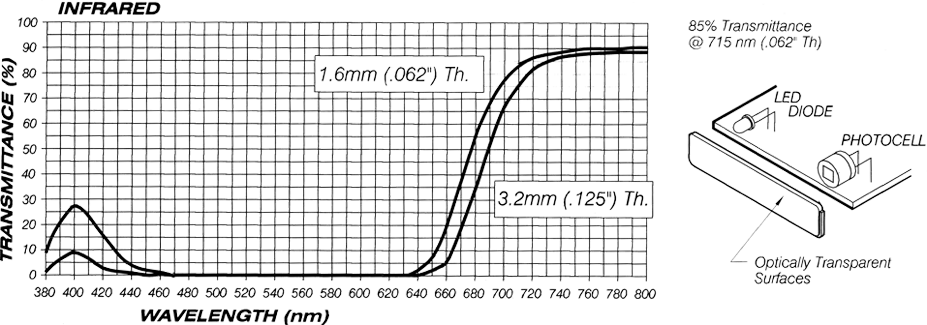
End Panels are available in Deep Violet for infrared transmission, Clear, and Transparent Red.
| End Panel Thickness | in | mm |
| A Series (excluding A42) | .060 | 1.52 |
| *A42 | .125 | 3.18 |
| End Panel Thickness | in | mm |
| H Series | .045 | 1.14 |
| M Series | .065 | 1.65 |


UL flame ratings group materials into categories based on their flammability. U.L. standard 94 defines two types of tests: vertical burn and horizontal burn. These tests lead to essentially six levels of ratings. Flammability tests cannot and do not measure material performance in a fire.
These tests lead to essentially six levels of ratings. Depending on your final use and environment of operation it is likely a U.L. standard will need to be met. Serpac can provide a custom material and certification for your needs.
The Horizontal Test (HB)
A specimen is supported in a horizontal position and is tilted at 45°. A flame is applied to the end of the specimen for 30 seconds or until the flame reaches the 1 inch mark. If the specimen continues to burn after the removal of the flame, the time for the specimen to burn between the 1 and 4 inch marks are recorded. If the specimen stops burning before the flame spreads to the 4 inch mark, the time of combustion and damaged length between the two marks is recorded. Three specimens are tested for each thickness.
HB Requirements
- Specimens must not have a burning rate greater than 1.5 inches/minute for thicknesses between 0.120 and 0.500 inches and 3 inches/minute for thicknesses less than 0.120 inches.
- Specimens must stop burning before the flame reaches the 4 inch mark.

Vertical Test (V-0, V-1, V-2)
A specimen is supported in a vertical position and a flame is applied to the bottom of the specimen. The flame is applied for ten seconds and then removed until flaming stops at which time the flame is reapplied for another ten seconds and then removed. Two sets of five specimens are tested. The two sets are conditioned under different conditions
V-0 Requirements
- Specimens must not burn with flaming combustion for more than 10 seconds after either test flame application.
- Total flaming combustion time must not exceed 50 seconds for each set of 5 specimens.
- Specimens must not burn with flaming or glowing combustion up to the specimen holding clamp.
- Specimens must not drip flaming particles that ignite the cotton.
- No specimen can have glowing combustion remain for longer than 30 seconds after removal of the test flame.
V-1 Requirements
- Specimens must not burn with flaming combustion for more than 30 seconds after either test flame application.
- Total flaming combustion time must not exceed 250 seconds for each set of 5 specimens.
- Specimens must not burn with flaming or glowing combustion up to the specimen holding clamp.
- Specimens must not drip flaming particles that ignite the cotton.
- No specimen can have glowing combustion remain for longer than 60 seconds after removal of the test flame.
V-2 Requirements
- Specimens must not burn with flaming combustion for more than 30 seconds after either test flame application.
- Total flaming combustion time must not exceed 250 seconds for each set of 5 specimens.
- Specimens must not burn with flaming or glowing combustion up to the specimen holding clamp.
- Specimens can drip flaming particles that ignite the cotton.
- No specimen can have glowing combustion remain for longer than 60 seconds after removal of the test flame.

Vertical Flame Test (5V Types)
Testing is done on both bar and plaque specimens.
A bar specimen is supported in a vertical position and a flame is applied to one of the lower corners of the specimen at a 20° angle. The flame is applied for 5 seconds and is removed for 5 seconds. The flame application and removal is repeated five times.

The procedure for plaques is the same as for bars except that the plaque specimen is mounted horizontally and a flame is applied to the center of the lower surface of the plaque.

5V Requirements
- Specimens must not have any flaming or glowing combustion for more than 60 seconds after the five flame applications.
- Specimens must not drip.
- Specimens must not be destroyed in the area of the flame.
5V-A Requirements
- Specimens must not have any flaming or glowing combustion for more than 60 seconds after the five flame applications.
- Specimens must not drip flaming particles that ignite the cotton.
- Plaque specimens must not exhibit burn through (a hole).
5V-B Requirements
- Specimens must not have any flaming or glowing combustion for more than 60 seconds after the five flame applications.
- Specimens must not drip flaming particles that ignite the cotton.
- Plaque specimens may exhibit burn through (a hole).
Optional End Panels For A-Series, M-Series & H-Series
End Panels are available in Deep Violet for infrared transmission, Clear and Transparent Red.
Clear And Transparent Red
Panel Characteristics
Dielectric Strength: 85 KV/mil
Continuous operating temperature: -50°C (-58°F) to 74°C (165°F)
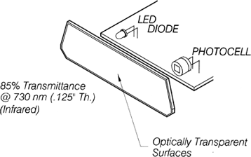
End Panel Thickness
For all IR, CL & TRANSPARENT
A-Series All A-Series end panels are .0601(1.52) except A-42 which is .125(3.18).
H-Series All H-Series end panels are .045(1.14).
M-Series All M-Series end panels are .065(1.65).
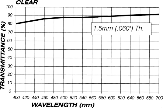
Infrared Panel Characteristics
Dielectric Strength: 380 V/mil
Continuous operating temperature: -129°C (-200°F) to 276°C (310°F)
